EQUIPMENT SELECTION
b) Face Supports
While it is frequently argued (correctly) that all items on a longwall face have to be considered as parts of an integrated unit and be fully compatible, it cannot be denied that poorly designed and inadequate roof supports are likely to have a greater effect on results than other items, and to that extent are more important. Inadequate shearer or AFC designs will usually only slow the face and reduce production (which may be financially disastrous) whereas inadequate support design may lead to loss of roof control with significant safety risks and damage to equipment as well as loss of production. Overdesign will avoid the risk of loss of control but at a cost and possibly will introduce other problems associated with size and weight.
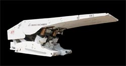
A thinner seam 2 leg support shown almost fully closed.
Photo courtesy of Joy Manufacturing Company Pty Ltd
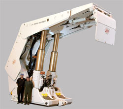
A support for a very thick seam shown fully extended.
Photo courtesy of Joy Manufacturing Company Pty Ltd
Support design/selection considerations should include:
- Ability to control the rate of closure of the mined opening i.e. strata control (mainly roof control but floor movement cannot be ignored). This will include setting and yield loads, support stiffness, hydraulic system pressures and support geometry;
- Load distribution on roof and floor strata, closely allied with the above but with different connotations;
- Hydraulic systems with regard to ease of operation, minimisation of potential leakage points, speed of operation (supports must be capable of being advanced at the same rate as the shearer cuts) and pressure requirements;
- Support operating height range to handle seam thickness variations and to enable transport around the mine when fully closed;
- Overall size and weight for transport purposes; and
- Ergonomic aspects both for operation (largely ease of travel along the face) and for maintenance/parts replacement purposes.
Cost has intentionally been excluded from the list of considerations. It may be a factor in deciding between two otherwise satisfactory offers or may be the deciding factor in continuing or abandoning a project. It should not be a consideration in determining the adequacy of support systems which should be a purely engineering exercise.
Most of the following comments are applied to roof movement which is usually the major concern, certainly from safety aspects, but it should not be forgotten that they can apply equally to floor movement. The roof may be controlled satisfactorily, but excessive closure of the face as a result of floor heave can still occur leading to major production losses.
The starting point for design/selection is to decide the support load requirement to maintain control of the roof, usually expressed as tonnes/m2, sometimes as tonnes/m run of face which ignores the area of the support. This will be an exercise in geomechanics and its success will depend greatly on the extent of knowledge of the resource to be worked. Some knowledge is required of coal and surrounding strata strengths, extent of discontinuities (joints, bedding planes, etc), depth of cover and stress magnitudes. Ideally information can be obtained from experience already gained at the mine concerned or from adjacent workings, but at a "greenfield" location some estimation will be necessary. With the large number of longwalls which have been worked it is likely that similar conditions will have been encountered elsewhere and useful information may be available.
Factors and methods involved in designing/evaluating support performance are well described by Mitchell(1) who in turn refers to work by C Wilkinson for Broadmeadow mine.
The degree of roof movement possible before failure occurs, usually considered to be in the range 15 to 35mm of sag(1), varies with roof material properties and must be determined or estimated for the given conditions.
The roof movement is made up of two parts, an initial largely uncontrollable portion which occurs before supports can have full effect and a portion which is allowed by the support during operation. Additional movement may occur if the support is inadequate and can lead to roof failure and loss of control.
There may be some degree of even earlier movement if gas drainage is used and removal of the gas pressure allows relaxation of the coal reducing the degree of restraint on roof and/or floor strata.
The initial movement starts as soon as the coal which previously supported and constrained the roof strata is removed and no support is in place to resist such movement, other than the bridging effect of strata supported by uncut coal ahead of the face and the supports set between the face and the goaf. This largely unrestrained freedom to move continues until supports are moved forward under this freshly cut roof and even then can continue while any clearances or looseness in the support structure connections are taken up and any broken material or any unevenness of the roof or floor crushes and allows full application of the support load to the strata. While this has been termed "uncontrollable" as there is no effective support immediately below the portion of roof in question, the supports and coal do provide an overall control system by providing the sides for the bridging effect, which does affect the stability of this otherwise unsupported roof.
The main control of the roof is provided by the supports once they are set below freshly exposed roof, so for best control it is obvious that the support should be brought forward and reset as soon as practical behind the shearer. If roof conditions are poor, the support should be brought forward almost immediately, but some methods of working require some delay before supports are advanced. There is no problem in this delay, provided the overall support system is designed to cater for it.
The attitude of the support is an important factor in providing this early application of load to the roof. With a rigid canopy, any unevenness or cavities in the roof can prevent the front of the canopy from touching the roof thus delaying any effective resistance to movement of that section of freshly exposed roof until either the support is advanced again or until roof movement closes the gap, this delay possibly leading to roof failure. Some supports have been provided with an articulated tip actuated by a small cylinder attached to the canopy to provide early tip load. Such loading is relatively low but can be effective in maintaining roof control.
However effective the support setting, this does not normally cause roof movement to cease (nor is it intended to as no support can provide enough load to do this) unless the stage is reached where the roof strata is bridging across the supports onto reconsolidated material in the goaf. After setting, further closure of the roof will occur (the second part of the two parts of roof movement referred to above) as the fluid in the support legs is compressed and dilation of the hydraulic system occurs. This will cause an increase in the hydraulic pressure above the setting pressure until this is relieved through valves at the designed support yield pressure. This continuous increase in pressure is the mechanism providing roof control, but it must be allowed to yield before damage to the support occurs.
To minimise roof movement, the setting pressure should be as close as practical to the yield pressure. It is not practical for them to be too close, and setting pressure (and reset pressure after yield occurs) is normally of the order of 95% of the yield pressure. The degree of movement involved in this process is referred to as the "stiffness" of the support, and for good roof control the stiffer the better. (A solid support rather than yielding would obviously provide the greatest stiffness but would not be able to be moved once loaded). The closer the reset pressure to the yield the more frequent is the yield/reset cycle which has an effect on the life of a support; supports are usually designed to last for a particular number of cycles taking into account the fatigue effect of continuous cycling.
Regarding the support geometry, to minimise the total support load to be provided, the shorter the support (in the face to goaf direction) the better, as less strata has to be supported. There must of course be adequate room to provide access for personnel to carry out production and maintenance operations, and space to contain the hydraulics and control equipment. Other factors to be considered however are the chock "aspect ratio" (the ratio of the support canopy length in front of the legs to the length behind the legs) and the bearing pressure on the strata. The aspect ratio affects the canopy tip load which can be applied and the attitude of the canopy, especially if strata crushing occurs at the goaf edge and it has been found that an aspect ratio of 2.6:1 or less is preferred (1). If the bearing pressure on the strata is too great, this can cause roof failure in itself, especially at the goaf edge where horizontal constraint is lost. A longer canopy may be required to reduce this bearing pressure, though it is rare for this to be a controlling factor in support design.
The load/m² provided by a support can be varied at the design stage by changing the area of the support canopy, though this is largely fixed for practical purposes. Load is most frequently varied at the design stage by changing the hydraulic pressure and/or the support cylinder diameter. In order to obtain the high pressures required on many faces it is common to have a two-pressure set, a lower set pressure (commonly at a pressure of the order of 320 bar) providing relatively high quantity, with a lower quantity high pressure set (of the order of 400-420 bar) to complete the operation. A higher load is more easily obtained by increasing the leg cylinder diameter, but this of course comes with increased cost and more difficult material handling if a leg replacement is required. As conditions become more onerous, both high pressure set and large leg diameters are required.
From the fact that support stiffness depends on the yield/reset cycle, it is readily apparent that leakage from the section of the hydraulics which is closed after resetting (the leg cylinders and controls) must be minimised. This becomes a vital component of support maintenance. Leakage from other parts of the hydraulic circuit will lead to wastage, increased pumping and fluid costs and to slower setting times. The latter can have some effect on roof control, but leakage from the closed section will lead to the worst consequences. There are advantages in being able to isolate individual legs on each support, allowing other legs to maintain their design capacity despite a leak on one leg. The ability to isolate and control legs individually can also assist in maintaining canopy alignment in the event of uneven roof conditions being encountered. This ability requires manual operation and means the automatic operation, if used, would have to be turned off, at least for that support or group of supports.
Because any looseness in support linkages has to be taken up before any pressure is applied to the roof, minimising this looseness by good maintenance is important to enable more rapid attainment of full set pressure during initial setting, but also to minimise misalignment between the support canopy and base, particularly in the thicker seams where such misalignment can become a serious problem. The misalignment can lead to an inability to obtain the full setting load and can lead to damage to legs, leg attachments and support structure.
Misalignment between canopy and base can also be caused by poor design and/or misuse of the support side shields. The side shields are intended to ensure a full cover of the roof when all supports are set in order to prevent loose material from falling between supports causing injury to personnel or damage to equipment. They are not intended to be used as an aid to steering of supports which may be tending to move down dip or towards the leading end of the face, and such use will lead to the misalignment problems noted above. This effect can occur unintentionally if the supports are tending to move in one direction and the side shield cylinders are allowed to provide their maximum push. To try and avoid the misuse of side shields, some supports are fitted with a spring to push the side shields into place, thus restricting the force which can be applied, and only use hydraulics to retract them. Others limit the extent of side movement available, but this can lead to larger than desirable gaps between supports, particularly in high seams.
- http://www.cdc.gov/NIOSH/mining/pubs/pdfs/dcftn.pdf - paper by T Bartzak of NIOSH on support design (undated but appears to have been written around 2000/2001
- System Behavior Analysis Of The Ground Movement Around A Longwall - paper on a method of longwall support design - payment required for full paper